How PainlessMesh Turns Your NodeMCU Into a Network That Heals Itself

You've probably built a project where one NodeMCU talks to your laptop over WiFi and thought this is great. But what if we need 10 sensors across a large building? And that's where the issues appear.
In this article, we'll discuss what happens after you outgrow a single WiFi node. We'll dive into PainlessMesh, a library that lets a group of ESP8266 NodeMCUs form a self-organizing, self-healing wireless network with almost no configuration.
We'll go deep on how it actually works, what the real-world limits are, and finish with working code you can flash today.
Why Star Networks Fail?
Before understanding what PainlessMesh solves, let's identify the problem.
The classic WiFi topology usualy our phone, laptop, etc. connect to a router. This is a star network.
One access point sits in the center, and all your devices connect to it.
Simple, familiar, fine for home use.
When we take esp8266 to form a network, it acts as an access point.
A single 2.4 GHz access point can comfortably manage around 6 to 8 stable client connections before you start seeing congestion, dropped packets, and latency spikes. That's it. Your entire "network" is bounded by one piece of hardware.
The obvious workaround is chaining multiple star networks together. Turning on one more access point in each room, connect them over Ethernet, problem solved right? right?
But not exactly, there are a few drawbacks:
Running Ethernet through walls across a factory floor or a large building is expensive and inflexible. Move a machine, re-run the cable.
Every node in a star network has exactly one parent (the access point).
If that access point goes down, every single device connected to it goes dark simultaneously. There's no fallback, no alternate route. The sub-network collapses entirely.
This means you're stuck making each access point location-specific.
The sensor near the window must talk to the access point in that room. If that access point has a power cut, you lose visibility into that entire zone even if every sensor in the zone is perfectly healthy.
That fragility is the core problem mesh networking was designed to eliminate.
What Is PainlessMesh?
PainlessMesh is an open-source Arduino library that turns any group of ESP8266 or ESP32 modules into a self-organizing WiFi mesh network.
The library is maintained by the community and available at:
https://gitlab.com/painlessMesh/painlessMesh
What makes PainlessMesh different from typical WiFi networks?
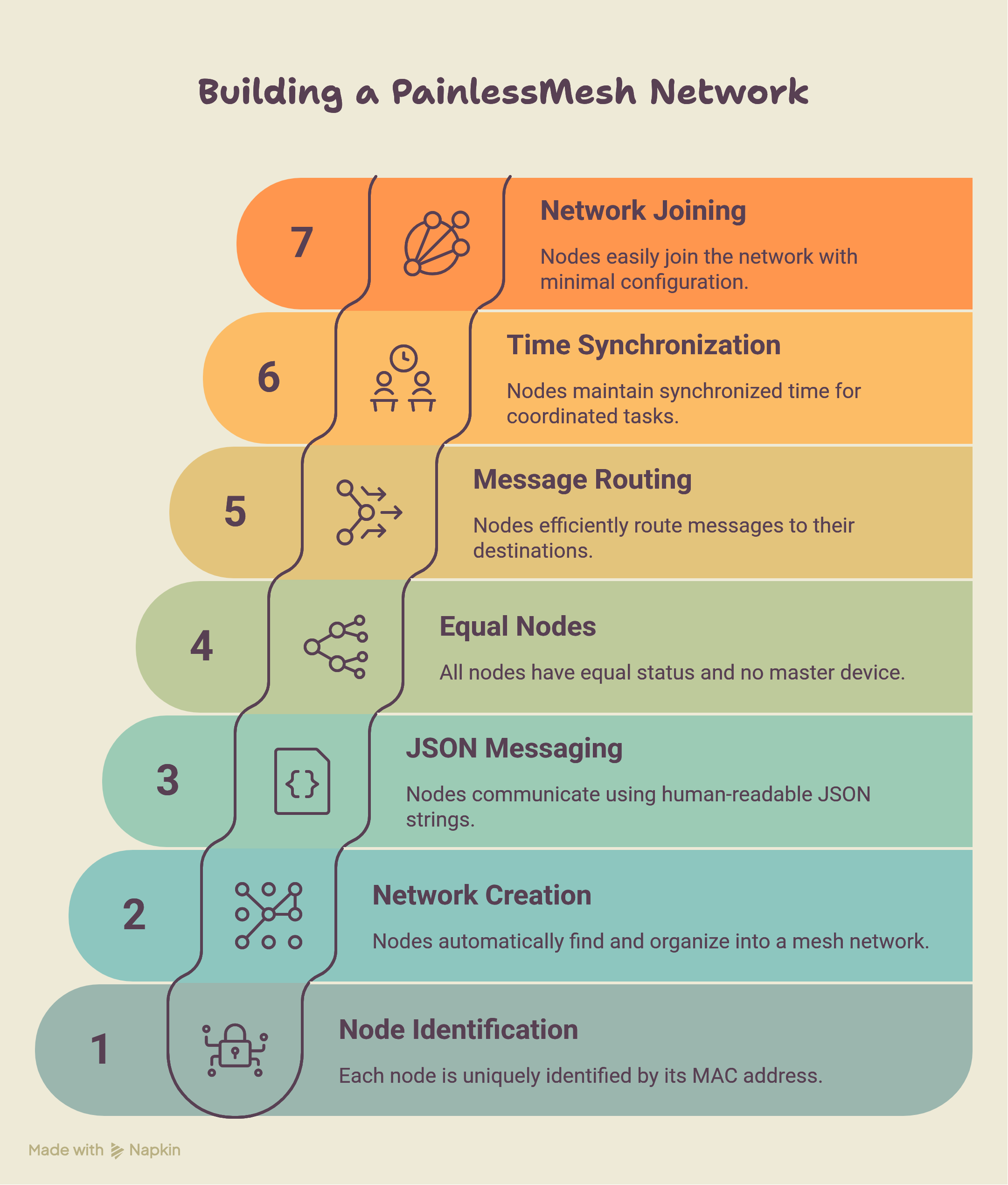
- PainlessMesh operates at Layer 3 of the OSI model but replaces IP with a 32-bit node ID derived from each chip's MAC address.
- Every node in the network is uniquely identified. No DHCP, no IP conflicts, no subnets to configure.
- The mesh creates its own WLAN. Nodes find each other, negotiate topology, and start routing, all without any external infrastructure.
- It uses JSON messaging. All messages between nodes are JSON strings.
- This makes the payload human-readable and easy to parse on any platform. The trade-off is overhead compared to raw binary, but for sensor data and control messages, the overhead is entirely acceptable.
- Every node is equal.
- There's no master device you configure separately. Every node runs the same library. The network elects a root node automatically and reorganizes if that root disappears.
- Messages can be sent in one of two ways: broadcast or unicast. A broadcast message reaches every node in the network. A unicast message goes to one specific node identified by its 32-bit ID.
- All nodes are time-synchronized to within 10 milliseconds. This is built into the library and lets you run synchronized tasks across nodes without any external clock.

How PainlessMesh Network Builds Itself?
When you power on a group of PainlessMesh nodes, you don't press a button or run a setup wizard.
The network constructs itself through a three-step process.
1. Root Node Election
Every idle node broadcasts a beacon packet containing its MAC address and its RSSI (signal strength) relative to the nearest external WiFi router. All nodes simultaneously scan for beacon packets from their neighbors.
If a node sees a beacon with a stronger router RSSI than its own, it forwards that beacon.
This continues for a minimum number of iterations (default: 10 rounds). After all rounds complete, every node tallies the vote counts. The node that receives votes from more than 90% of the network (default threshold) becomes the root node — also called the sink node. This node directly interfaces with any external network or router.
The root can also be manually assigned by the programmer using mesh.setRoot(true). When a root is manually defined, the voting mechanism is bypassed entirely.
2. Layer Formation
Once the root is established, idle nodes in its vicinity connect to it, forming the second layer. Those second-layer nodes then become available as access points for third-layer nodes to connect to.
The network grows outward, layer by layer, like a tree.
Nodes closer to the root carry traffic for nodes farther away — they act as intermediate nodes, routing packets from deeper in the mesh toward the root and back.
3. Limiting Tree Depth
The network enforces a maximum tree depth. Nodes at the deepest allowed layer become terminal nodes — they don't allow new nodes to connect through them.
This prevents the topology from growing uncontrollably deep, which would increase hop count and latency for every packet traveling from leaf to root.

How Every Node Works?
The ESP8266 on NodeMCU can operate in three WiFi modes:
Station mode (STA), Access Point mode (AP), or both at the same time (AP+STA).
Most projects use only STA mode where module connects to your home router as a client.
PainlessMesh uses AP+STA simultaneously.
What this means in practice:
- The AP side of the node acts as a mini access point. Other nodes connect to it as stations.
- The STA side of the node connects to another node's AP.
So every node is simultaneously a client of one node above it (its parent) and a server for nodes below it (its children).
This is what creates the multi-hop routing capability.
A message from a leaf node travels up through intermediate nodes each one forwarding it until it reaches the root.
No external access point is required because every node is an access point. The mesh is entirely self-contained.
Each Node Updates Every 3 Seconds
Here's something that surprises most people: every node in a PainlessMesh network knows the complete network topology not just its immediate neighbors, but the entire graph of who is connected to whom.
This is kept current by a topology sync that runs every 3 seconds. Each node tells its neighbors about every other node it knows about, directly or indirectly. Neighbors propagate that information further. Within a few cycles, every node has a consistent view of the full network.
This is what enables intelligent routing. When a unicast message needs to travel from node A to node G, the library already knows the path it doesn't need to probe or discover it on the fly. The routing table is already cached.
The 3-second update cycle is also what drives self-healing. When a node disappears, the topology sync detects the inconsistency within the next cycle and triggers a reconfiguration.
What Happens When a Node Dies?
Self-healing is the most impressive behavior of PainlessMesh, and it works differently depending on which node fails.
Root Node Failure
When the root node goes offline, every second-layer node detects the disconnection. They initially attempt to reconnect. After several failed attempts, the second-layer nodes trigger a fresh election they broadcast their router RSSIs and vote for a new root. The second-layer node with the strongest router RSSI wins. The remaining second-layer nodes establish upstream links to the new root, and the network is back.
In real-world testing on a college campus deployment, the measured healing time after sink node failure was 4.18 seconds. The network was back routing traffic in under five seconds.
Intermediate Node Failure
When an intermediate node fails, its children detect the disconnection and attempt to reconnect. If they can't reach the failed node, they scan for alternative intermediate nodes within range and re-attach. If no alternative exists for a particular end node, that end node becomes idle — but the rest of the network continues functioning normally.
The measured healing time after an intermediate node failure was 3.46 seconds — slightly faster than root failure recovery because it doesn't require a full re-election.

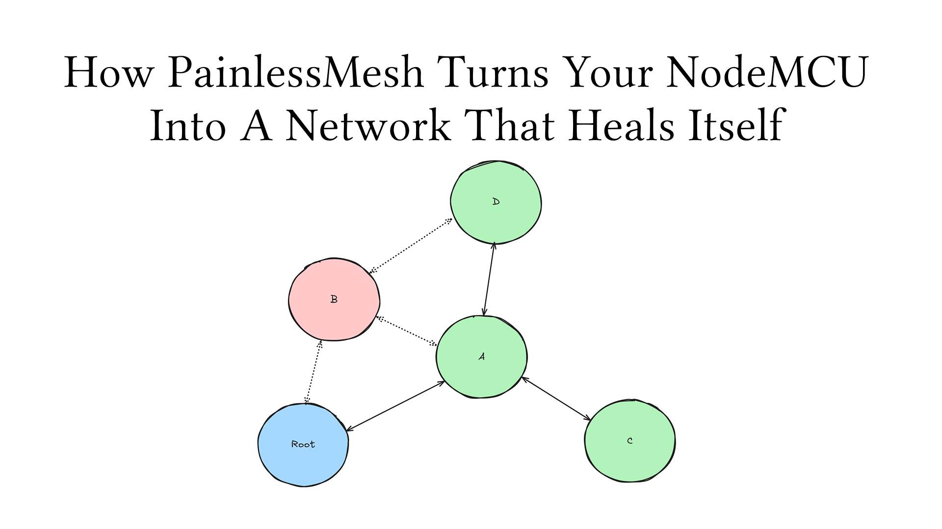
A Real Example
Imagine nodes arranged as: Root → B → E.
If B fails, E loses connectivity. E scans for nearby nodes. If node C is within range, E connects to C.
The topology is now Root → C → E. One node failed. The network adapted. No human intervention, no configuration change.
How It works in Real World
After checking few research paper on test result here is what I found.
One-Way Delay
In a two-node network (the simplest possible case), the one-way delivery delay has a median of 2.49 ms. This is the best you'll ever get — treat it as the performance ceiling for a single hop.
As you add nodes, the delay increases — even for packets traveling the same number of hops. A 10-node network shows noticeably higher delays than a 3-node network for 1-hop messages. The reason is that more nodes means more background topology sync traffic, more memory pressure on the ESP8266, and more contention on the 2.4 GHz channel.
Delivery Ratio
Under light load (1 message per second), delivery ratios are consistently above 90% regardless of payload size. This is the sweet spot for sensor-monitoring use cases.
At 5 messages per second, performance varies significantly based on payload size. The payload size that consistently performed best across all node counts was 250 bytes — because it fits efficiently within the 536-byte Maximum Segment Size window used by the library's TCP stack.
At 10 messages per second, delivery ratios drop sharply, often falling below 50% for larger payloads. High message rates overwhelm the ESP8266's limited processing resources.
Practical guideline: keep your send rate at 1 message per second or below for reliable operation. Use payloads under 250 bytes where possible.
The Payload Limit:
The ESP8266 has a hard limit. Payloads larger than 4400 bytes cause incomplete and corrupted messages. Below that threshold, the library handles fragmentation. Above it, messages arrive broken.
For reference, at a 10-byte payload, a receiver can process up to 461 messages per second. At a 4400-byte payload, that drops to 28 messages per second. The chip simply isn't fast enough to process large messages at high rates.
Campus-Scale Deployment Results
In a real deployment across a college campus covering a 100 × 80 meter area with 7 nodes, the results were:
- Rate of Packet Delivery (RPD): > 97% for most nodes
- Packet Fault Rate (PFR): < 1.8% for most nodes
- Packet Loss Rate (PLR): < 1.8% for most nodes
- Network build time: 17.32 seconds from power-on to fully connected
The outlier was the furthest node, placed 100 meters from the root across four buildings and walls — it showed slightly higher fault and loss rates, likely due to signal attenuation through structural barriers.
| Metric | Value |
|---|---|
| 2-node one-way delay | 2.49 ms |
| Healing after root failure | 4.18 s |
| Healing after intermediate failure | 3.46 s |
| Network build time | 17.32 s |
| Max payload before corruption | 4,400 bytes |
| Max messages/sec at 10-byte payload | 461 |
| Max messages/sec at 4400-byte payload | 28 |
| Optimal payload size | ~250 bytes |
| RPD in campus deployment | > 97% |
| Topology sync interval | 3 seconds |
What type of message painlessmesh supports?
PainlessMesh supports two message types and choosing the wrong one wastes bandwidth fast.
mesh.sendBroadcast(msg) — Sends the message to every node in the network. Every intermediate node retransmits it. Use this when all nodes need the information — for example, a configuration update or a network-wide alarm.
mesh.sendSingle(nodeId, msg) — Sends the message to one specific node identified by its 32-bit ID. Intermediate nodes route it but don't process it as their own message. Use this when you're sending data from a specific sensor to the gateway, or sending a command to a specific actuator.
For a typical sensor network, sendBroadcast is tempting because it's simpler — you don't need to know the destination ID. But in a 10-node network, every broadcast generates 9 additional transmissions. With sensors reporting every second, that's significant overhead. Use sendSingle for point-to-root sensor data whenever the destination ID is known.
How Many Nodes Can You Actually Run?
The library doesn't publish a hard limit, and the creator acknowledges the theoretical maximum is very high due to the amount of memory that can be allocated for sub-connections. But the ESP8266's hardware imposes a practical ceiling.
Research papers tells us the inflection point:
- 2–3 nodes: Stable, low latency, high delivery ratios. Ideal for simple projects.
- 4–10 nodes: Stable in open environments without walls. Delivery ratios remain good at low message rates.
- 16 nodes: Notably unstable. During testing, a 16-node network frequently failed to get all nodes to join a single mesh. Individual nodes would form isolated sub-networks. The instability becomes more pronounced as you add more nodes.
The root cause is the ESP8266's limited RAM. Each node maintains the full network topology in memory. As the network grows, the topology table grows, and background sync traffic increases. At some point, the chip runs out of headroom.
If you need more than 10–12 nodes, consider moving to ESP32 it has significantly more RAM and processing power, and PainlessMesh supports it natively. The ESP32 campus deployment referenced in research ran 7 nodes reliably across a real building with > 97% delivery.
For large deployments, another approach is segmenting into multiple independent meshes one per building or zone each with its own SSID, password, and port. Each mesh has a root node that aggregates data from its zone and forwards it upstream.
Asynchronous Power-On: Why Boot Order Changes Your Topology
This one catches people off guard in real deployments. PainlessMesh networks don't always look the same when nodes boot at different times.
Consider this scenario:
- Your root node (best RSSI) powers on last, five minutes after all the other nodes.
- By that time, the other nodes have already held an election and chosen a different root.
- When your intended root finally boots, it doesn't trigger a new election it simply connects to the existing network as a regular node.
The network works, but it's topologically different from what it would be if everything powered on simultaneously. Your designated root is now an intermediate or end node.
Three conditions govern late-booting nodes:
- If a root already exists, the late node joins as a regular member, no new election, even if it has a better RSSI.
- If the late node becomes an intermediate node, nearby nodes may switch their upstream link to use it as their parent.
- If a late node has a manually assigned intermediate parent that hasn't booted yet, it stays idle indefinitely waiting for its assigned parent.
Practical implication: In installations where boot order matters (a gateway that needs to be root), either power it on first, or use mesh.setRoot(true) to force root assignment and bypass the election entirely.
How To Use PainlessMesh?
Let's build the simplest useful example: one sensor node that reads temperature and humidity from a DHT11 sensor and sends it to a gateway node that prints the received data to the Serial console.
Install the Library
In the Arduino IDE, install:
painlessMeshby Coopdis, Scotty Franzyshen, Edwin van Leeuwen, Germán MartínArduinoJsonby Benoit BlanchonTaskSchedulerby Anatoli Arkhipenko
Core API You Need to Know
Before the full code, understand these five building blocks:
// Initialize the mesh
mesh.init(MESH_SSID, MESH_PASSWORD, &scheduler, MESH_PORT);

// Register callback — fires when this node receives a message
mesh.onReceive(&receivedCallback);

// Register callback — fires when a new node joins the network
mesh.onNewConnection(&newConnectionCallback);

// Send to every node in the mesh
mesh.sendBroadcast(message);

// Send to one specific node
mesh.sendSingle(nodeId, message);

// Must be called in loop() — drives all mesh operations
mesh.update();
Every node in your mesh must call mesh.update() every loop iteration. Without it, the mesh library can't process incoming packets, run the topology sync, or maintain connections. Never put a delay() in your loop() — use the TaskScheduler instead.
Sensor Node Code
This node reads temperature and humidity (simulating a DHT11) and broadcasts readings every 5 seconds.
/**
 * sensor_node.cpp
 * PainlessMesh Sensor Node
 *
 * Joins the mesh and broadcasts temperature + humidity
 * every 5 seconds to the gateway node.
 *
 * Hardware: NodeMCU v2 (ESP8266) + DHT11 on pin D2
 */

#include <Arduino.h>
#include <painlessMesh.h>
#include <ArduinoJson.h>
#include <DHT.h>

// ── Mesh credentials (must match gateway) ────────────────────────
#define MESH_SSID     "MyMeshNetwork"
#define MESH_PASSWORD "meshpassword123"
#define MESH_PORT     5555

// ── Sensor config ─────────────────────────────────────────────────
#define DHT_PIN  D2
#define DHT_TYPE DHT11

// ── Globals ───────────────────────────────────────────────────────
Scheduler scheduler;
painlessMesh mesh;
DHT dht(DHT_PIN, DHT_TYPE);

// ── Send sensor data every 5 seconds ─────────────────────────────
Task taskSendData(5000, TASK_FOREVER, []() {
  float temperature = dht.readTemperature();
  float humidity    = dht.readHumidity();

  if (isnan(temperature) || isnan(humidity)) {
    Serial.println("[sensor] Failed to read from DHT11");
    return;
  }

  // Build a simple JSON message
  JsonDocument doc;
  doc["node"]  = mesh.getNodeId();   // unique 32-bit ID of this node
  doc["temp"]  = temperature;
  doc["hum"]   = humidity;

  String msg;
  serializeJson(doc, msg);

  mesh.sendBroadcast(msg);

  Serial.printf("[sensor] Sent → %s\n", msg.c_str());
});

// ── Mesh callbacks ────────────────────────────────────────────────
void receivedCallback(uint32_t from, String &msg) {
  // Sensor node doesn't expect messages — ignore
}

void newConnectionCallback(size_t nodeId) {
  Serial.printf("[mesh] New node connected: %u\n", (uint32_t)nodeId);
}

void changedConnectionCallback() {
  Serial.println("[mesh] Topology changed");
}

// ── Setup ─────────────────────────────────────────────────────────
void setup() {
  Serial.begin(115200);
  delay(100);

  dht.begin();

  mesh.setDebugMsgTypes(ERROR | CONNECTION);
  mesh.init(MESH_SSID, MESH_PASSWORD, &scheduler, MESH_PORT);
  mesh.onReceive(&receivedCallback);
  mesh.onNewConnection(&newConnectionCallback);
  mesh.onChangedConnections(&changedConnectionCallback);

  // Register and start the data task
  scheduler.addTask(taskSendData);
  taskSendData.enable();

  Serial.printf("[sensor] Node ID: %u — waiting for mesh...\n",
                mesh.getNodeId());
}

// ── Loop ──────────────────────────────────────────────────────────
void loop() {
  mesh.update(); // Never skip this
}
Gateway Node Code
This node receives all messages from the mesh and prints them to Serial. Flash this to your second NodeMCU and keep it connected to your laptop via USB.
/**
 * gateway_node.cpp
 * PainlessMesh Gateway Node
 *
 * Acts as the root of the mesh network.
 * Receives data from all sensor nodes and
 * prints it to the Serial console.
 *
 * Hardware: NodeMCU v2 (ESP8266)
 */

#include <Arduino.h>
#include <painlessMesh.h>
#include <ArduinoJson.h>

// ── Mesh credentials (must match sensor node) ─────────────────────
#define MESH_SSID     "MyMeshNetwork"
#define MESH_PASSWORD "meshpassword123"
#define MESH_PORT     5555

// ── Globals ───────────────────────────────────────────────────────
Scheduler scheduler;
painlessMesh mesh;

// ── Mesh callbacks ────────────────────────────────────────────────
void receivedCallback(uint32_t from, String &msg) {
  Serial.printf("\n[gateway] Message from node %u\n", from);
  Serial.printf("[gateway] Raw: %s\n", msg.c_str());

  // Parse the JSON
  JsonDocument doc;
  DeserializationError err = deserializeJson(doc, msg);

  if (err) {
    Serial.printf("[gateway] JSON parse error: %s\n", err.c_str());
    return;
  }

  float temp = doc["temp"];
  float hum  = doc["hum"];

  Serial.printf("[gateway] Temperature : %.2f °C\n", temp);
  Serial.printf("[gateway] Humidity    : %.2f %%\n", hum);
  Serial.println("[gateway] ─────────────────────────");
}

void newConnectionCallback(size_t nodeId) {
  Serial.printf("[mesh] +Node joined: %u\n", (uint32_t)nodeId);
  Serial.printf("[mesh] Total nodes: %d\n", mesh.getNodeList().size() + 1);
}

void droppedConnectionCallback(size_t nodeId) {
  Serial.printf("[mesh] -Node left: %u\n", (uint32_t)nodeId);
}

void changedConnectionCallback() {
  Serial.println("[mesh] Topology updated");
}

// ── Setup ─────────────────────────────────────────────────────────
void setup() {
  Serial.begin(115200);
  delay(100);

  // Tell the library this node is the root
  mesh.setDebugMsgTypes(ERROR | CONNECTION);
  mesh.setRoot(true);         // this node is the designated root
  mesh.setContainsRoot(true); // tell other nodes the root is in this network

  mesh.init(MESH_SSID, MESH_PASSWORD, &scheduler, MESH_PORT);
  mesh.onReceive(&receivedCallback);
  mesh.onNewConnection(&newConnectionCallback);
  mesh.onDroppedConnection(&droppedConnectionCallback);
  mesh.onChangedConnections(&changedConnectionCallback);

  Serial.printf("[gateway] Root node ID: %u\n", mesh.getNodeId());
  Serial.println("[gateway] Waiting for sensor nodes...");
}

// ── Loop ──────────────────────────────────────────────────────────
void loop() {
  mesh.update(); // Never skip this
}
Expected Serial Output on the Gateway
Once both nodes are running, open the Serial Monitor on the gateway at 115200 baud:
[gateway] Root node ID: 3748291034
[gateway] Waiting for sensor nodes...
[mesh] +Node joined: 2918374651
[mesh] Total nodes: 2

[gateway] Message from node 2918374651
[gateway] Raw: {"node":2918374651,"temp":28.50,"hum":65.00}
[gateway] Temperature : 28.50 °C
[gateway] Humidity    : 65.00 %
[gateway] ─────────────────────────

[gateway] Message from node 2918374651
[gateway] Raw: {"node":2918374651,"temp":28.60,"hum":64.80}
[gateway] Temperature : 28.60 °C
[gateway] Humidity    : 64.80 %
[gateway] ─────────────────────────
The gateway node prints every reading as it arrives. To add a third node, flash the sensor node code to another NodeMCU with the same credentials. It joins automatically. No changes to the gateway, no configuration — the mesh self-organizes.
Conclusion
PainlessMesh lives up to its name by abstracting away the complex routing, topology sync, and self-healing logic that makes traditional mesh networks incredibly difficult to implement from scratch.
By using the simultaneous AP+STA capabilities of the ESP8266, it allows you to build robust, distributed IoT applications without the need for expensive infrastructure or complex cabling.
However, as the research and real-world metrics show, there are certain boundaries you must respect while using ESP8266.
- Keep the network size below 10–12 nodes when using ESP8266 (or transition to the ESP32 for larger deployments).
- Keep data transmission rates at or below 1 message per second.
- Restrict payloads to under 250 bytes to avoid TCP segmentation issues and memory pressure.
If you use within these limits, PainlessMesh provides an incredibly reliable, self-organizing foundation for home automation, environmental sensing, and local telemetry.
References
-
Khan, A.U. et al. An Efficient Wireless Sensor Network Based on the ESP-MESH Protocol for Indoor and Outdoor Air Quality Monitoring. Sustainability 2022, 14, 16630.
-
Santos, L. et al. Performance Assessment of ESP8266 Wireless Mesh Networks. Information 2022, 13, 210.
-
Yoppy et al. Performance Evaluation of ESP8266 Mesh Networks. J. Phys.: Conf. Ser. 1230 (2019) 012023.
-
Nurmiainen, O. Smart Manufacturing Utilizing Mesh Network Technology. Metropolia University of Applied Sciences, Bachelor's Thesis, 2024.
-
PainlessMesh Library Documentation — https://gitlab.com/painlessMesh/painlessMesh