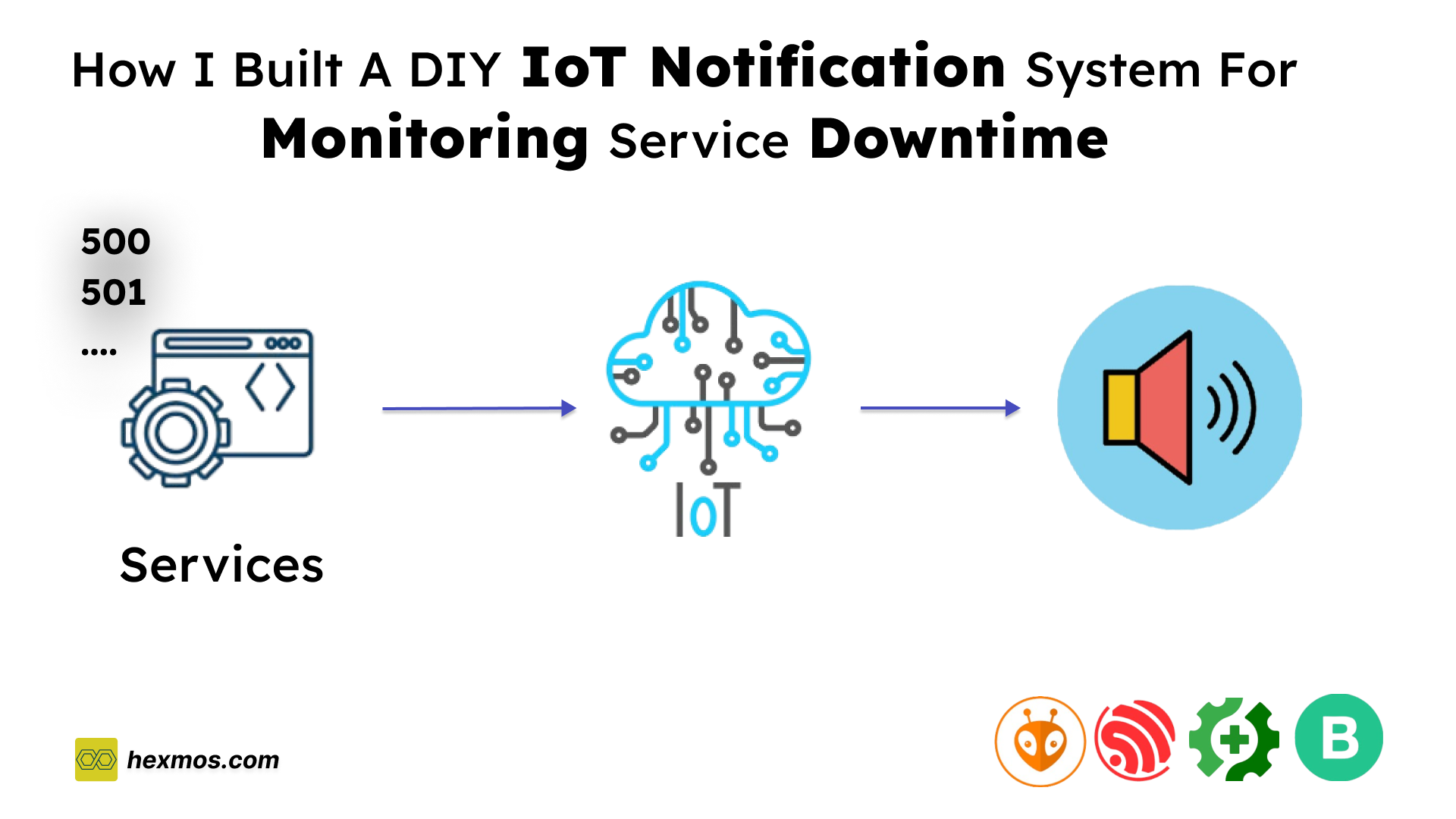
How I Built a DIY IoT Notification System for Monitoring Service Downtime
Want to know instantly when your services go down? Traditional notifications can be missed, especially at night. Here's how I built an IoT solution to solve this issue
We’re a small team building LiveAPI, a super-convenient tool that streamlines engineering workflows by generating API docs from your code in just minutes.
With our fast-paced approach of rolling out new features daily, ensuring our services stay online has always been a top priority.
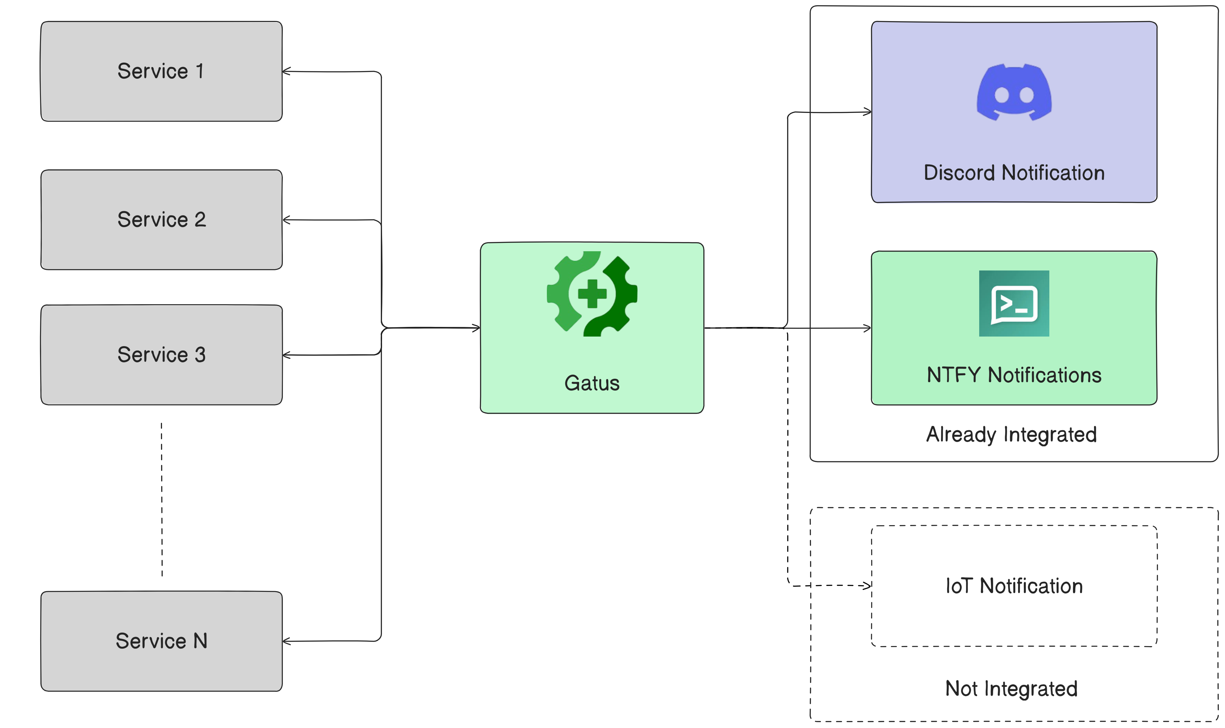
To monitor downtime, we Initially integrated Gatus with Discord webhooks.
It worked for a while, but we had an incident after deploying changes to the login system. The sign-in service went down. Even with three backups running in parallel, we missed the alert as it went down in the middle of the night.
That’s when it became clear to us only Discord Notification is not enough.
We upgraded by adding ntfy for push notifications. It is working. We wanted to experiment to see if we could do it with any speaker that is always on and cannot be ignored. That’s when I thought, "Why not use IoT for service alerts?"
In this article, I’ll walk you through how I made this work, from concept to implementation.
How The IoT Alert System Should Work
My Goal is to ensure that I receive a sound notification whenever one of my services goes down. Even during the night or when I’m not actively checking notifications.
To achieve this, I needed a way to bridge my existing monitoring tool, Gatus, with an IoT device capable of producing a sound alert.
We had already integrated with Gatus Discord notification I just need to use this webhook functionality to inform an IoT device, which will then produce an audible alert to catch attention immediately.
This means I needed a microcontroller with built-in Wi-Fi is essential. With the ability to connect to a network and interact with the webhook, the microcontroller serves as the perfect bridge between Gatus and the sound alert system.
Now that the logic is clear, the next step is selecting the perfect microcontroller and designing the system to meet these requirements.
To bring the idea to life, selecting the right microcontroller and designing an efficient connection setup is crucial.
The microcontroller must meet the requirements of being cost-effective, reliable, and capable of connecting to the internet.
Hardware Selection: Choosing the ESP32 Microcontroller
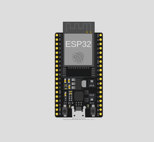
After exploring various options, I chose the ESP32 CP210x microcontroller for this project. This microcontroller is a popular choice for IoT applications because of its built-in Wi-Fi module, low power consumption, and versatility.
It supports multiple protocols, making it ideal for receiving webhook notifications. Additionally, its ease of programming and compatibility with various development tools make it beginner-friendly and highly customizable.
The ESP32 also features enough GPIO pins to connect external components, such as a buzzer or speaker, which will be used to produce the sound notification.
hence made it the perfect candidate for creating a reliable alert system.
Key Components and Connections
The connection design involves integrating the ESP32 with the required components to ensure the system can function as intended.
- Wi-Fi Connectivity: The ESP32 connects to the internet via Wi-Fi.
- Sound Output: A buzzer or small speaker is connected to one of the GPIO pins. This component is used to produce a loud sound when the ESP32 processes the webhook notification.
- Power Source: The ESP32 is powered via a USB cable or battery, depending on whether the system is stationary or portable.
- Programming Interface: The microcontroller is programmed through its CP210x USB-to-Serial interface, which simplifies flashing firmware and debugging.
With the microcontroller and connections in place, the next step is to set up the development environment and configure the system logic.
With the hardware chosen and the design outlined, the next step is to set up the development environment.
Setting Up the Development Environment
To program and configure the microcontroller efficiently, I chose VS Code as the development environment. VS Code offers a powerful, lightweight platform with excellent support for IoT projects, thanks to its rich ecosystem of extensions and plugins.
How I set up the environment:
- Install VS Code: Download and install VS Code from the official website.
- Add the PlatformIO Extension: I used the PlatformIO IDE extension because of its robust features for embedded development. Alternatively, the Arduino IDE is also a good choice for beginners. Both IDEs provide tools for writing, compiling, and uploading code to the microcontroller.
-
Configure the ESP32 Development Environment:
Configure the USB-to-Serial drivers to ensure seamless communication with the microcontroller.
For the CP210x interface, the drivers can be downloaded from the manufacturer's website. -
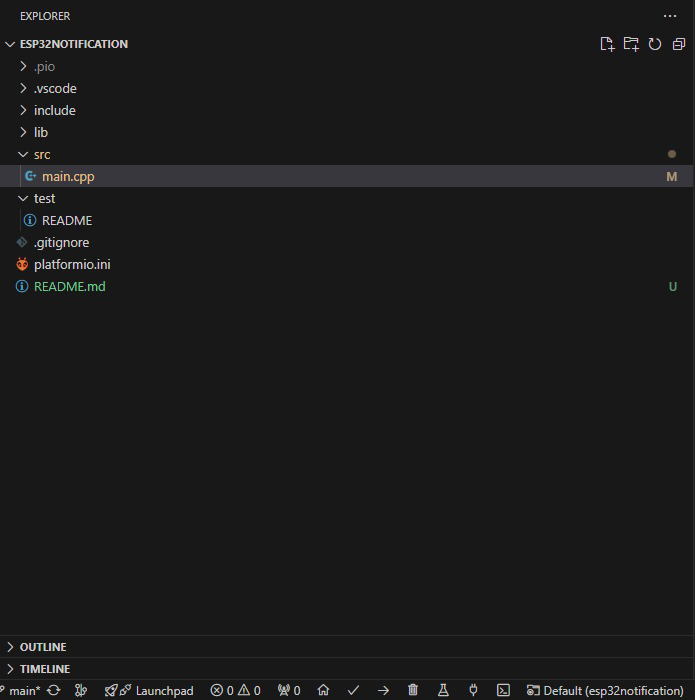
Set Up the Project: Create a new project folder in VS Code, initialize it with the selected extension, and select the appropriate board settings for the ESP32.
This setup ensures that the development process is smooth and efficient, enabling quick iterations and debugging.
I recommend going through this video where he has explained the full setup briefly.
With the IDE ready, the next step is to dive into programming the logic that connects the IoT device to the monitoring system.
Testing With Normal Blinking Light Program
Before implementing the full logic for the IoT notification system, it’s a good idea to test the setup with a basic program. A blinking light program is a perfect starting point to verify that the microcontroller, IDE, and connections are working correctly.
What the Program Does
The blinking light program toggles an LED on and off at regular intervals. Most microcontrollers, including the one used in this project, have a built-in LED connected to one of their GPIO pins (often labeled as "LED_BUILTIN" in the code). This simple test ensures that:
- The microcontroller is functioning properly.
- The code compiles and uploads successfully using the IDE.
- The microcontroller can execute the program as intended.
Steps to Test:
- Write the Code
Open your project in VS Code and create a basic program to toggle the LED. Below is an example:
#include <Arduino.h>

void setup() {
  pinMode(LED_BUILTIN, OUTPUT);
  Serial.begin(921600);

  Serial.println("Hello World");
}

void loop() {
    delay(1000);
    digitalWrite(LED_BUILTIN, HIGH);
    Serial.println("Inside loop");
    delay(1000);
    digitalWrite(LED_BUILTIN, LOW);

}
-
Upload the Code
Compile and upload the program to the microcontroller using the IDE. Ensure the correct board and port settings are selected in the IDE preferences. -
Verify the Output
Once uploaded, observe the built-in LED on the microcontroller. It should blink on and off at one-second intervals, confirming that the setup is working correctly.
Integrating with Monitoring Tools
As I mentioned earlier, the ESP32 requires Wi-Fi to connect to the internet. Since the ESP32 doesn't come with an out-of-the-box Wi-Fi setup, I used the WiFiManager library to simplify the process of connecting the device to a Wi-Fi network.
This library allows for a seamless configuration of the network credentials without hardcoding them into the code, making the setup more user-friendly and flexible.
Establishing Wi-Fi Connectivity with WiFiManager
#include <WiFi.h>
#include <WiFiManager.h>

// Initialize WiFiManager
WiFiManager wifiManager;

// Automatically connect or start a configuration portal
if (!wifiManager.autoConnect("ESP32_Config_AP")) {
    Serial.println("Failed to connect to WiFi. Restarting...");
    delay(3000);
    ESP.restart();
}

// Print connected WiFi details
Serial.println("WiFi connected successfully!");
Serial.print("IP Address: ");
Serial.println(WiFi.localIP());
- Purpose: Handles Wi-Fi configuration without hardcoding credentials.
- Process:
- If previously saved credentials exist, it connects automatically.
- Otherwise, it starts a configuration portal (
ESP32_Config_AP) to allow manual network setup.
- Fallback: If the device fails to connect, it restarts after 3 seconds.
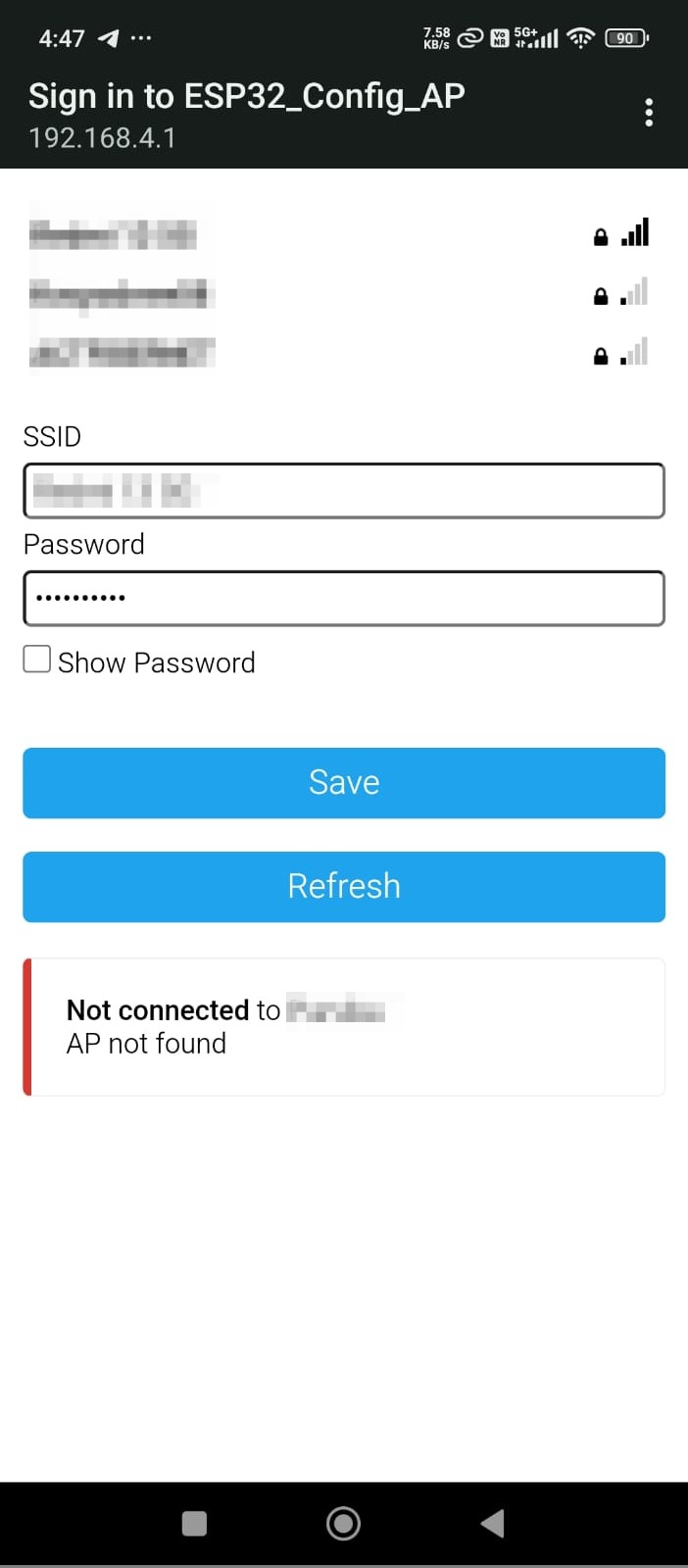
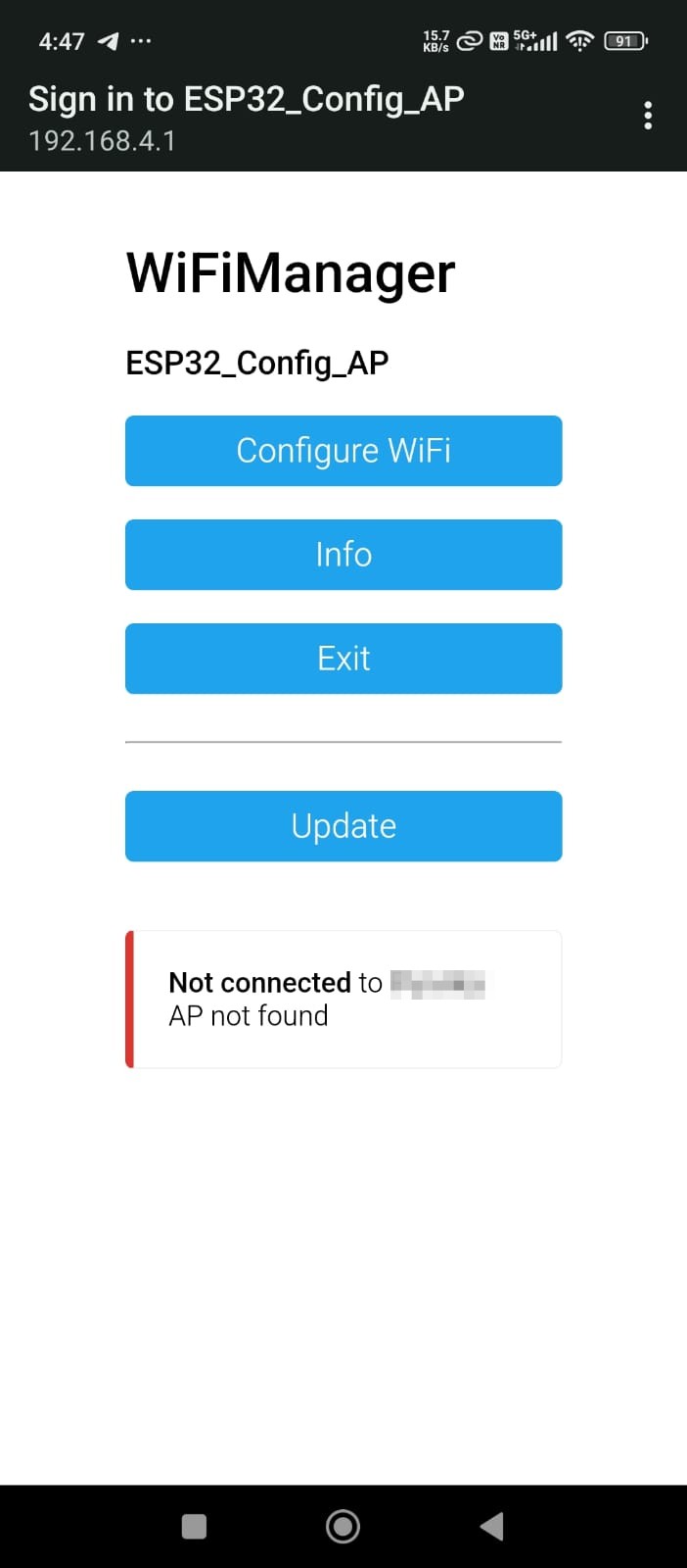
Once connected to the internet, the next step was to integrate a webhook system for sending and receiving notifications.
Building a webhook from scratch would have been time-consuming, so I opted for Blynk, a platform that provides an easy-to-use webhook feature.
With Blynk, I was able to quickly set up a basic system with a single switch to control the buzzer and send notifications.
Configuring Blynk for Webhook Notifications
How I set up Blynk for my IoT notification system. You can follow these steps to achieve the same results:
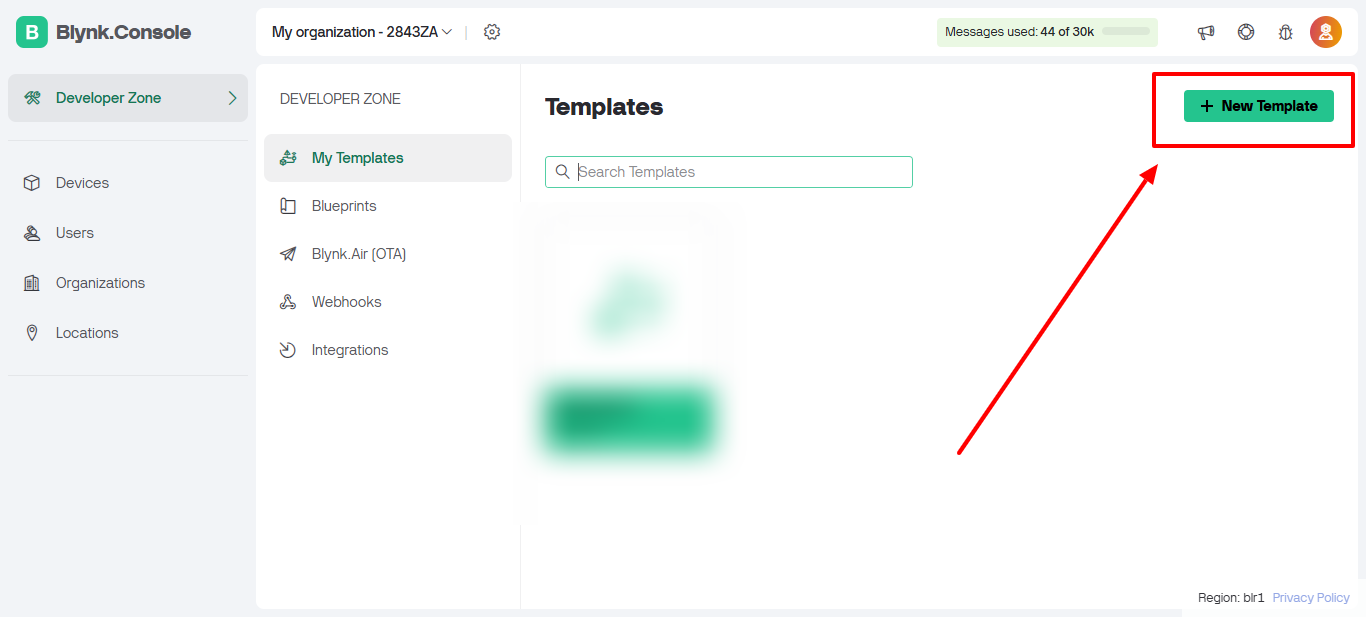
Step 1: Log in to Blynk. Upon logging in, you will be directed to the dashboard.
Click on the Developer Zone.
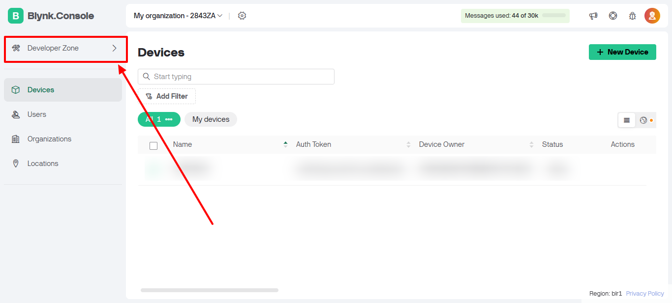
Step 2: Click on New Template.
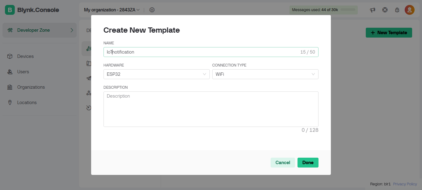
Step 3: Enter a name for your template.
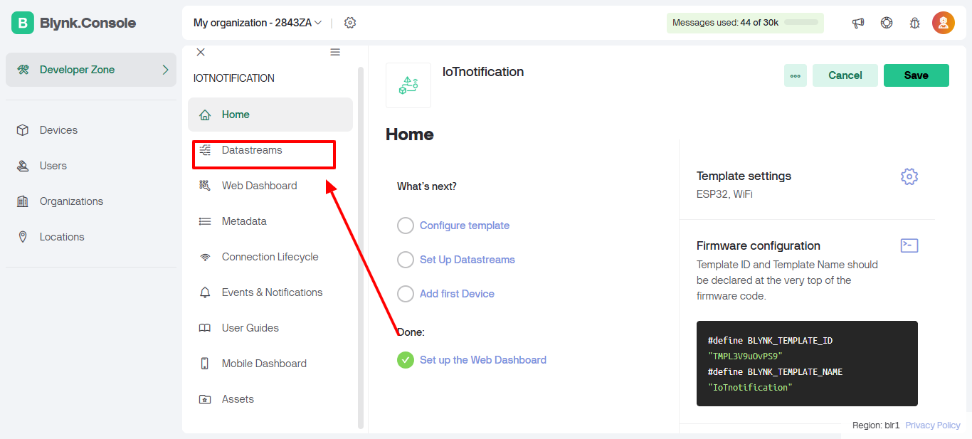
Step 4: On the template homepage, click on DataStreams.
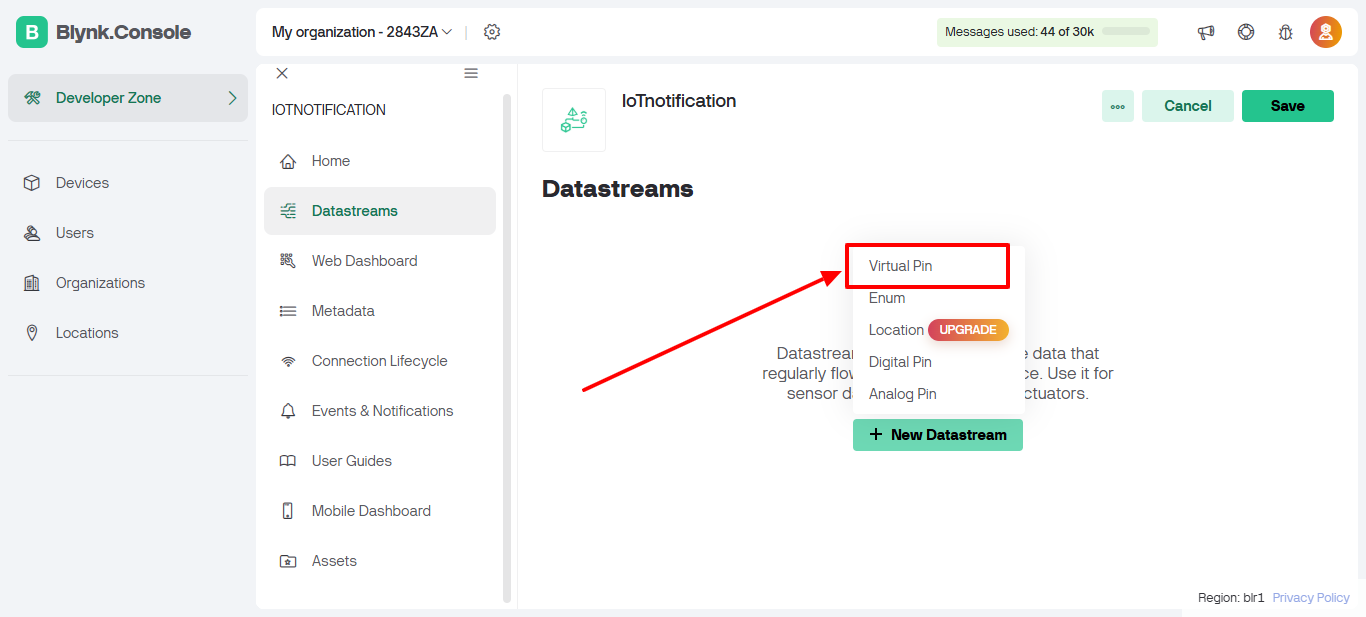
Step 5: Click on New DataStream.
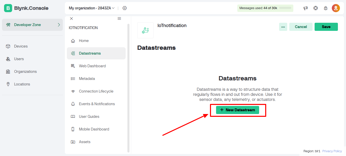
Step 6: Select Virtual Pin as the data stream type.
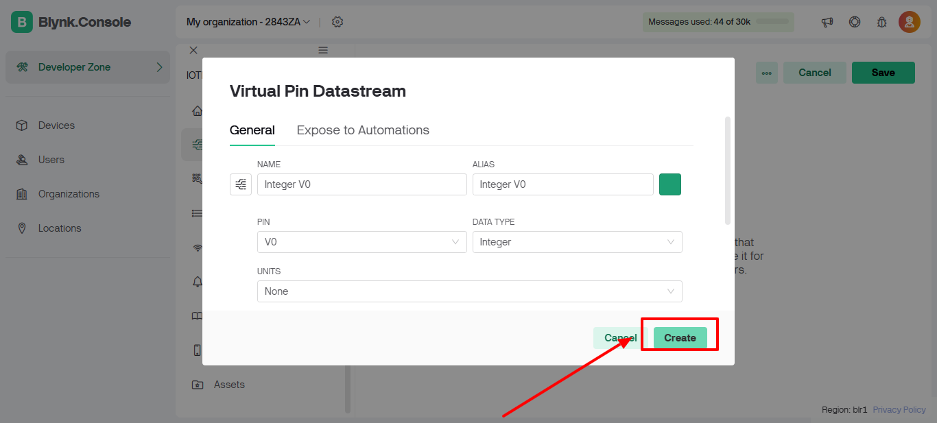
Step 7: Click on the Create button to save the data stream.
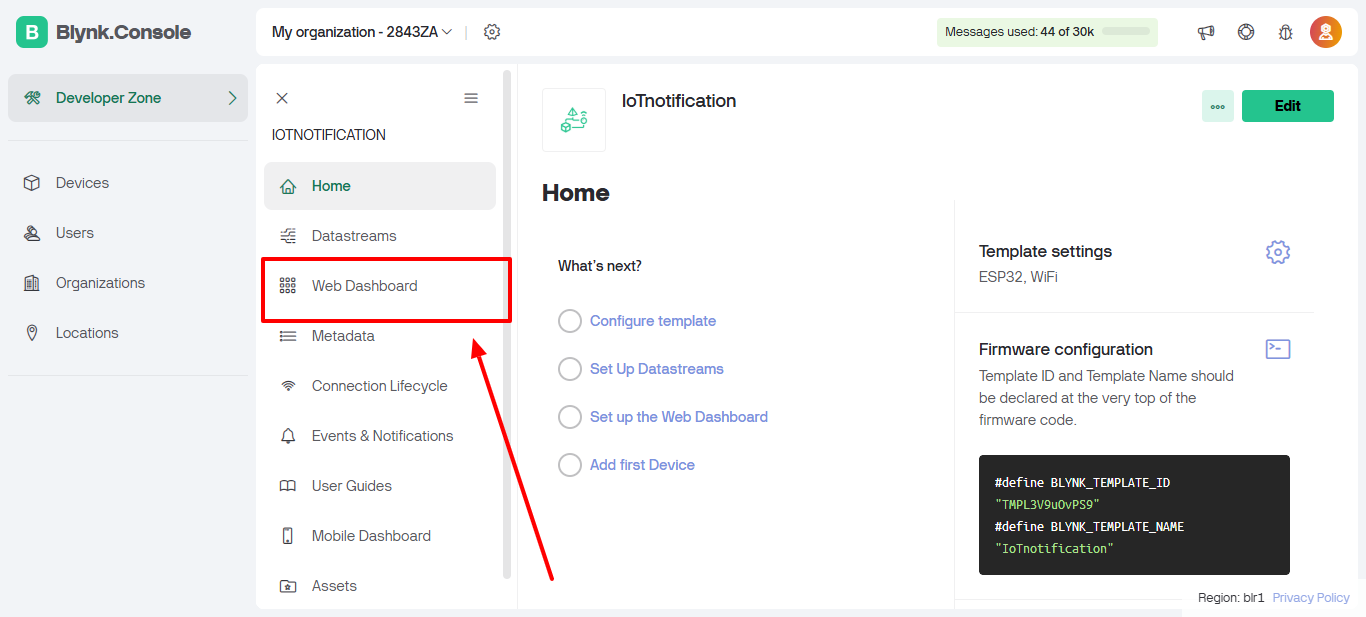
Step 8: Navigate to the Web Dashboard tab.
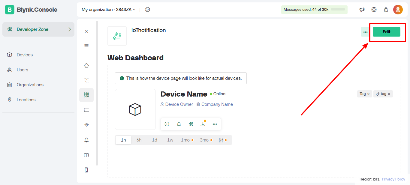
Step 9: Click on the Edit button to modify the dashboard layout.
Step 10: Drag and drop a Switch Button onto the dashboard.
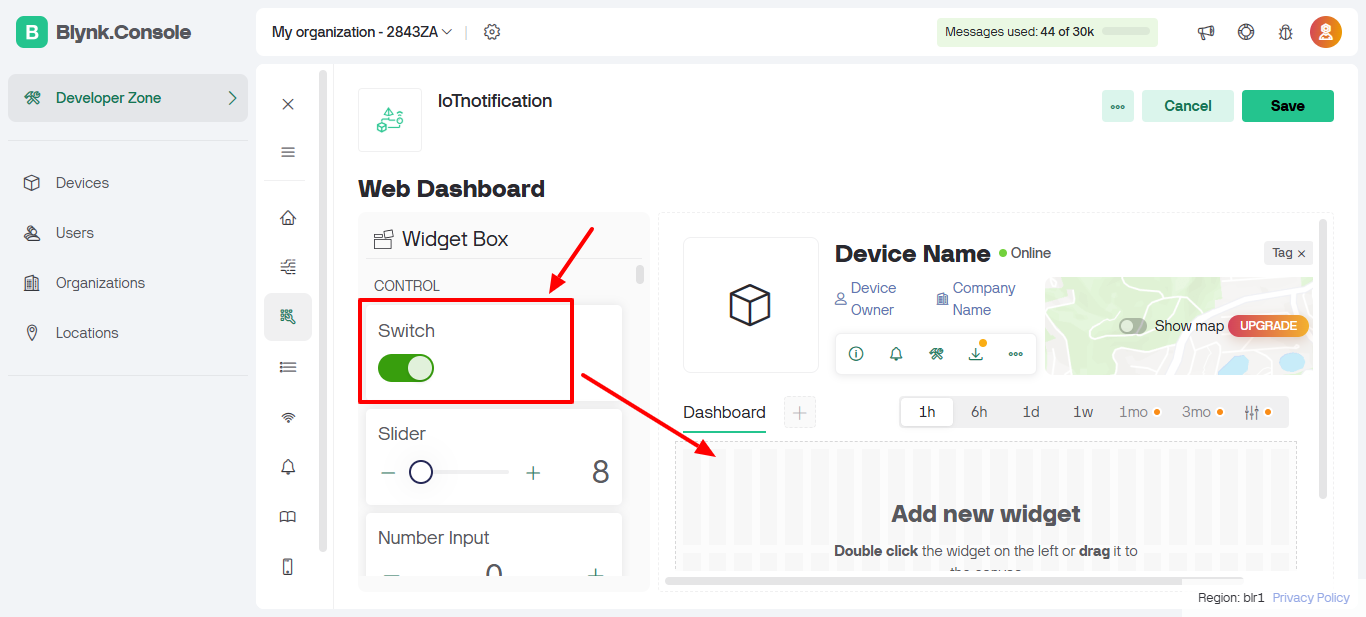
Step 11: Hover over the switch to reveal the Settings button. Click on it.
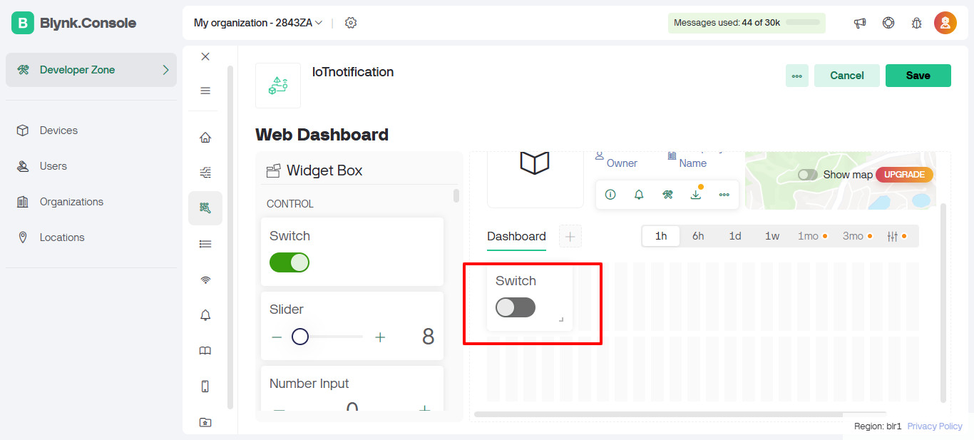
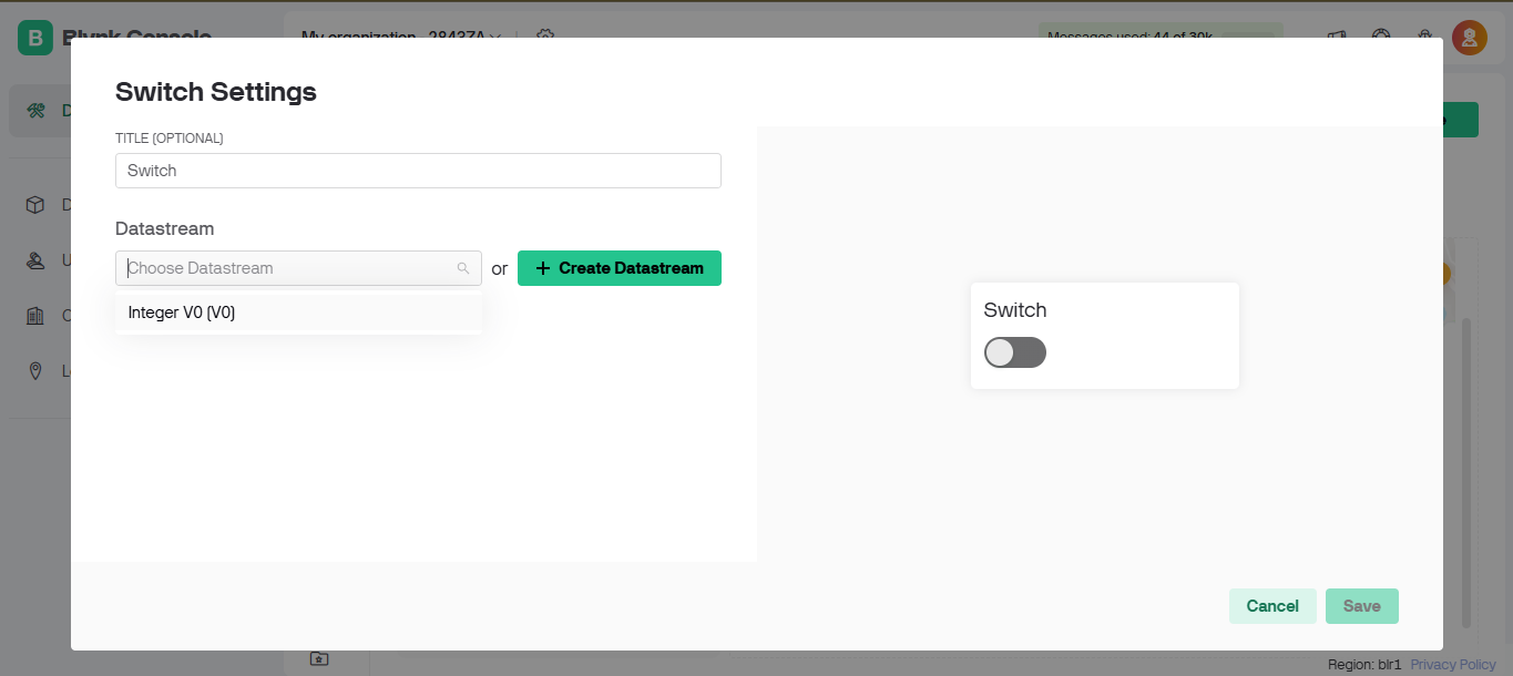
Step 12: In the settings, select the data stream you recently created.
Step 13: Click the Save button to save the settings.
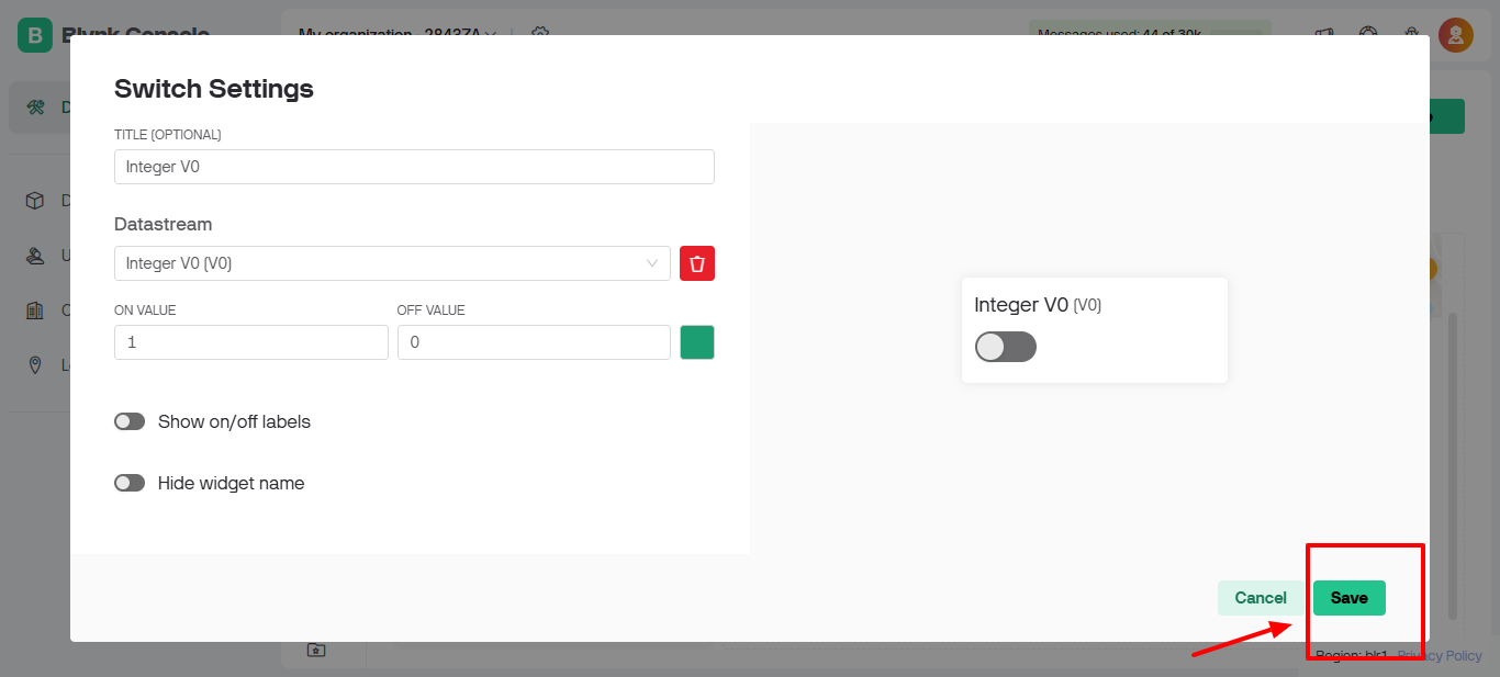
Step 14: Don’t forget to click on the Save button in the top-right corner to save the overall dashboard changes.
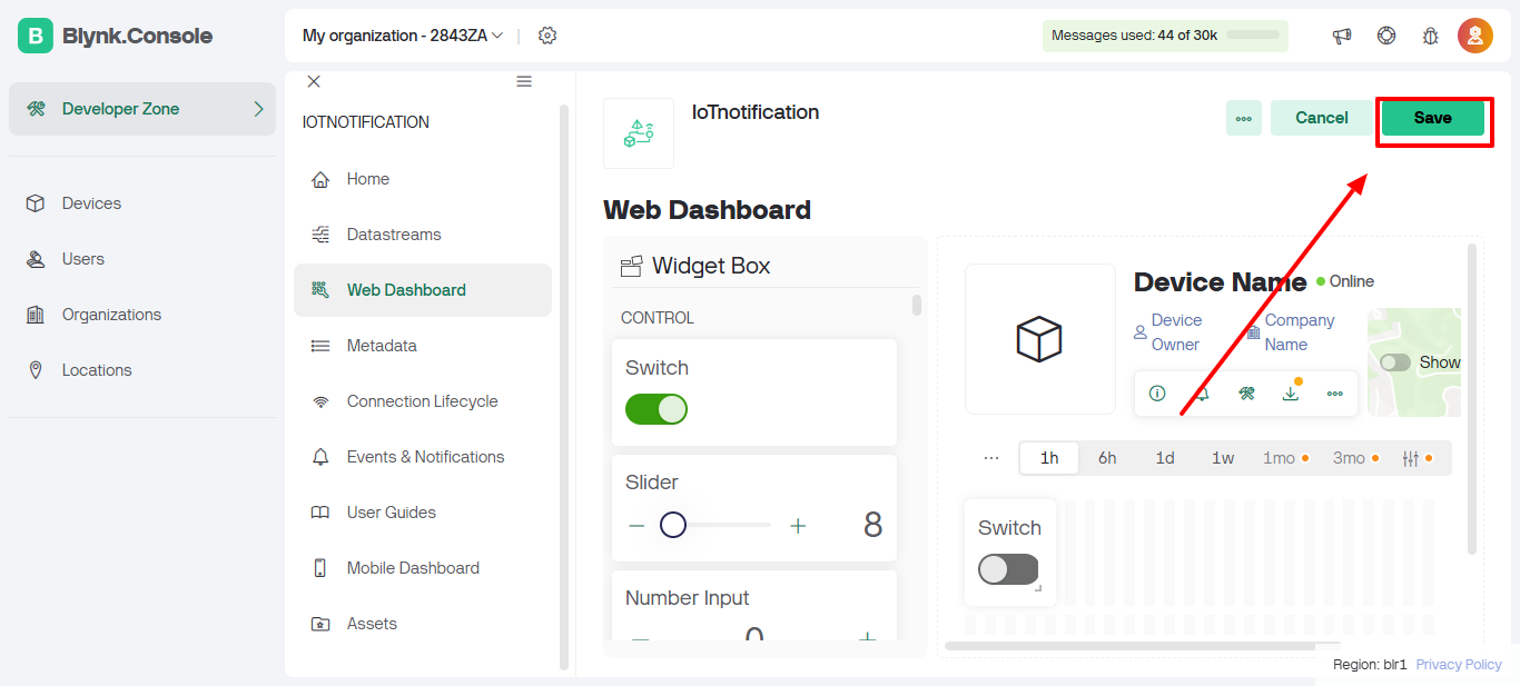
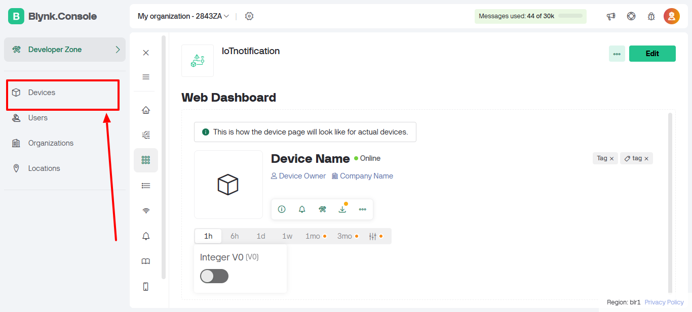
Step 15: Navigate to the Devices tab.
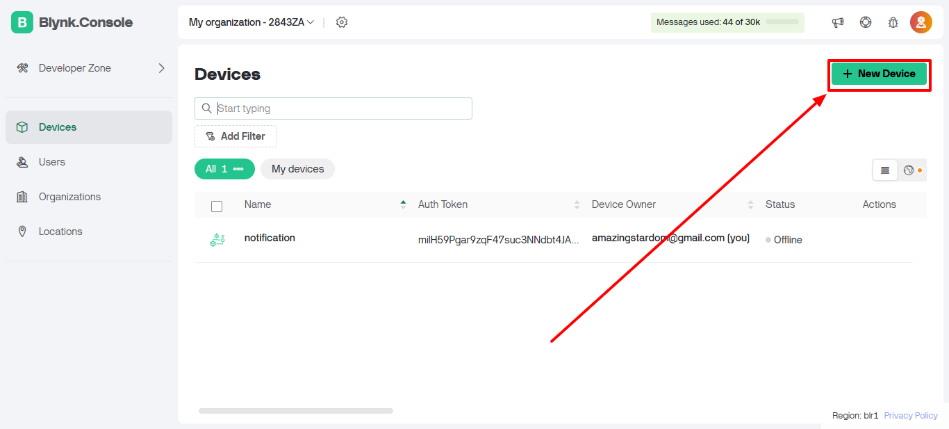
Step 16: Click on New Device to create a device.
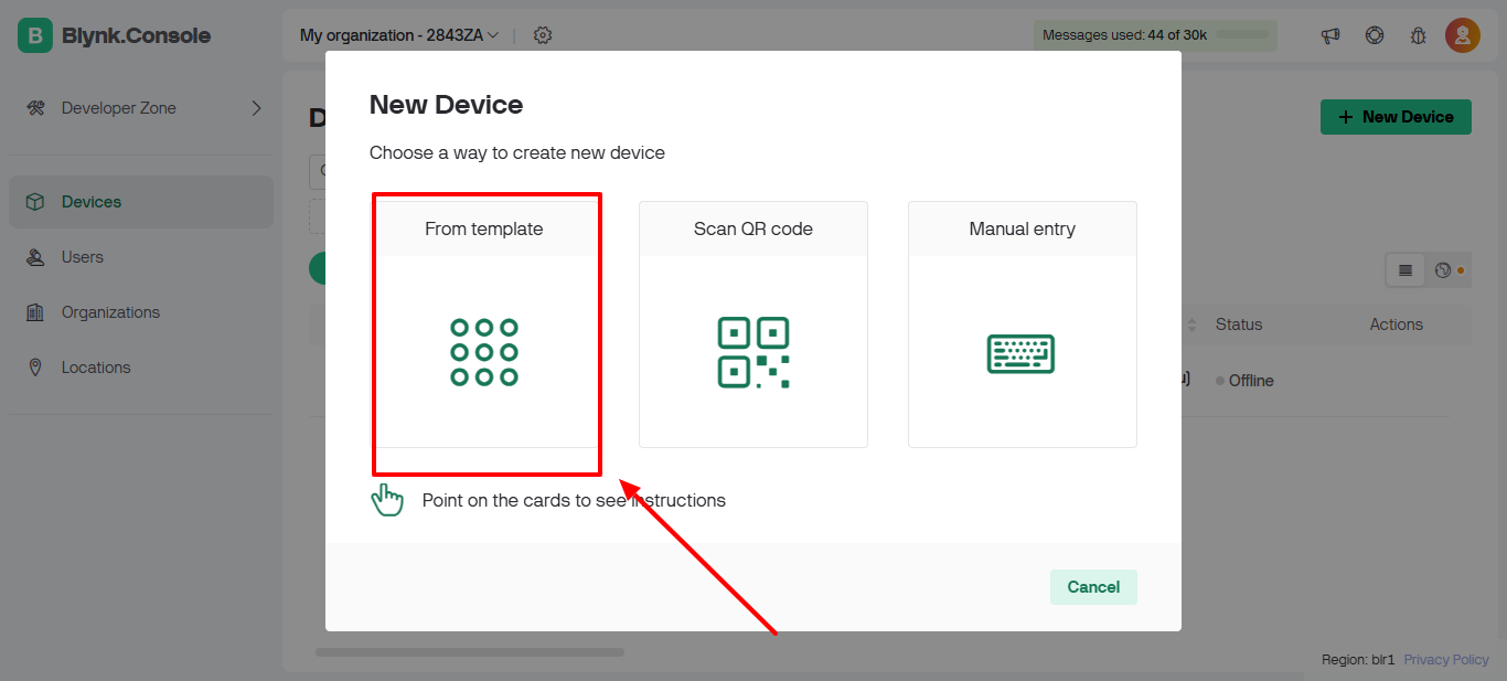
Step 17: Select From Template as the device type.
Step 18: Choose the template you created earlier.
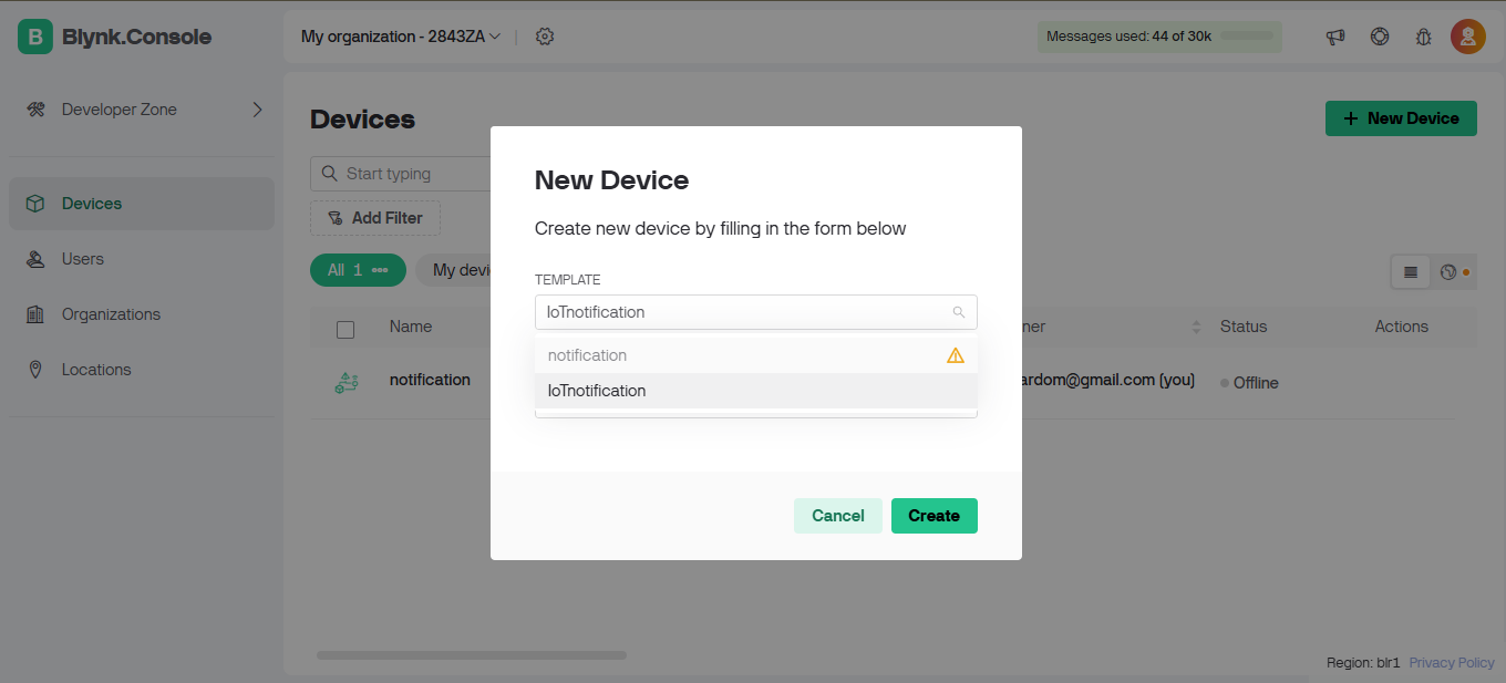
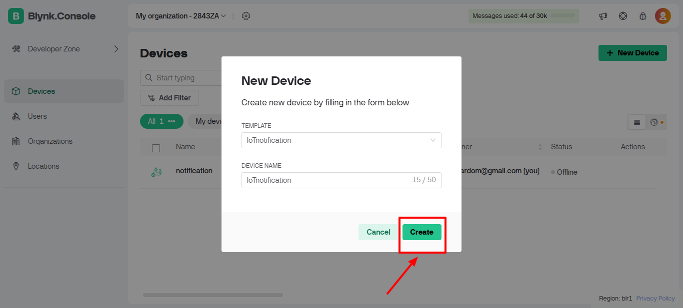
Step 19: Click on the Create button to finalize the device creation.
Step 20: Copy the credentials generated for the device. These credentials will be required for integrating the IoT device with Blynk.
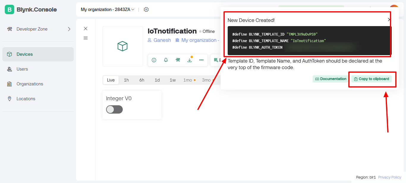
With these steps, your Blynk setup is complete! You can now integrate these credentials into your ESP32 code to start controlling your IoT device.
To get started with Blynk, I configured my ESP32 with the following setup:
#define BLYNK_TEMPLATE_ID "{BLYNK_TEMPLATE_ID}"
#define BLYNK_TEMPLATE_NAME "notification"
#define BLYNK_AUTH_TOKEN "{BLYNK_AUTH_TOKEN}"
The BLYNK_TEMPLATE_ID and BLYNK_AUTH_TOKEN were obtained from the Blynk dashboard during the project setup. This ensured that my ESP32 could securely communicate with the Blynk servers.
Blynk Integration Code
#include <BlynkSimpleEsp32.h>

#ifndef BLYNK_TEMPLATE_ID
#define BLYNK_TEMPLATE_ID "{BLYNK_TEMPLATE_ID}"
#endif
#ifndef BLYNK_DEVICE_NAME
#define BLYNK_DEVICE_NAME "notification"
#endif
#ifndef BLYNK_AUTH_TOKEN
#define BLYNK_AUTH_TOKEN "{BLYNK_AUTH_TOKEN}"
#endif

char auth[] = BLYNK_AUTH_TOKEN;

// Initialize Blynk
Blynk.begin(auth, WiFi.SSID().c_str(), WiFi.psk().c_str());
- Purpose: Connects the ESP32 to the Blynk cloud platform for IoT controls.
- Key Components:
BLYNK_TEMPLATE_IDandBLYNK_AUTH_TOKEN: Credentials from the Blynk dashboard.Blynk.begin: Initializes the connection using the ESP32's Wi-Fi credentials.
- Outcome: Enables virtual pin (
V0) communication for controlling devices like the buzzer and LED.
LED and Buzzer Setup
// Define pins for LED and buzzer
const int ledPin = 2;  // Built-in LED
const int buzzerPin = 13;  // GPIO 13 for the buzzer

// Set pins as outputs
pinMode(ledPin, OUTPUT);
pinMode(buzzerPin, OUTPUT);

// Initialize PWM for the buzzer
ledcSetup(0, 1000, 8);  // 1000Hz frequency, 8-bit resolution
ledcAttachPin(buzzerPin, 0);  // Attach PWM to buzzer pin
- Purpose: Set up the hardware components:
- LED for visual notifications.
- Buzzer for audible alerts.
- PWM on Buzzer: Controls the buzzer's frequency and intensity for tone generation.
Buzzer Control Logic
unsigned long previousMillis = 0; // Tracks the last buzzer state change
const long onDuration = 500;      // Buzzer ON time (500ms)
const long offDuration = 400;     // Gap between buzzer sounds (400ms)
bool buzzerState = false;         // Tracks whether the buzzer is ON or OFF
bool ledState = false;            // Tracks whether the LED is ON or OFF

// Buzzer control in the `loop`
if (ledState) { // If LED is ON
    unsigned long currentMillis = millis();
    if (buzzerState) {
        if (currentMillis - previousMillis >= onDuration) {
            ledcWrite(0, 0); // Turn buzzer OFF
            previousMillis = currentMillis;
            buzzerState = false;
        }
    } else {
        if (currentMillis - previousMillis >= offDuration) {
            ledcWrite(0, 128); // Turn buzzer ON (50% duty cycle)
            previousMillis = currentMillis;
            buzzerState = true;
        }
    }
} else {
    ledcWrite(0, 0); // Ensure buzzer is OFF when LED is OFF
}
- Purpose: Alternates the buzzer's state (ON/OFF) based on the LED's status.
- Details:
- Timers:
onDurationandoffDurationdefine the buzzer's sound pattern. - PWM Control: Adjusts the buzzer's tone when it’s ON.
- State Management: Ensures the buzzer stops immediately when the LED is turned OFF.
- Timers:
Blynk Virtual Pin Handler
BLYNK_WRITE(V0) {
    int value = param.asInt();  // Get value from Blynk app (0 or 1)

    // Update LED state based on Blynk input
    ledState = value ? true : false;
    digitalWrite(ledPin, ledState ? HIGH : LOW);

    if (ledState) {
        // Start toggling buzzer when LED is ON
        buzzerState = true;
        previousMillis = millis();
    } else {
        // Stop buzzer when LED is OFF
        ledcWrite(0, 0);
        buzzerState = false;
        Serial.println("Buzzer OFF (LED OFF)");
    }
}
- Purpose: Handles input from the Blynk app on virtual pin
V0to control the LED and buzzer. - Functionality:
- Turns the LED ON/OFF based on the value received (1 = ON, 0 = OFF).
- Starts/stops the buzzer toggling cycle based on the LED state.
Blynk Webhook Implementation: Controlling the Buzzer
To implement the alert system, I used Blynk's webhook functionality to control the buzzer. Here are the endpoints for turning the buzzer on and off:
With this two creds you can use webhook
Turn Off Buzzer:
https://{REGION}.blynk.cloud/external/api/update?token={BLYNK_AUTH_TOKEN}&v0=0
Turn On Buzzer:
https://{REGION}.blynk.cloud/external/api/update?token={BLYNK_AUTH_TOKEN}&v0=1

With these webhooks, I could trigger notifications or alerts whenever required.
Overcoming Development Challenges and Optimizations
During the integration process, I encountered challenges related to the ESP32's memory constraints, which prevented successful deployment of the firmware. Initially, I was using the following build configuration in the platformio.ini file:
; PlatformIO Project Configuration File

[env:nodemcu-32s]
platform = espressif32
board = nodemcu-32s
framework = arduino
monitor_speed = 921600
While this setup worked for basic projects, it failed during the build process for more complex features like Blynk integration and additional libraries due to insufficient flash memory allocation and lack of optimizations.
Challenges Faced:
-
Flash Memory Allocation:
The default partition table was too small to accommodate the program's binary, especially when integrating libraries and additional functionality like webhooks. -
Unoptimized Build Flags:
Debugging and unoptimized code increased the binary size, pushing it beyond the limits of the ESP32's allocated memory.
Optimized Build Configuration
After researching ESP32 memory optimization techniques and experimenting with various settings, I updated the platformio.ini file to include optimizations that allowed successful deployment:
; PlatformIO Project Configuration File

[env:nodemcu-32s]
platform = espressif32
board = nodemcu-32s
framework = arduino
monitor_speed = 921600

; Add these lines to increase flash size and optimize the build
; Larger flash partition for better use of ESP32 flash
board_build.partitions = huge_app.csv
; Optimization flags for smaller binary
build_flags =
    -DCORE_DEBUG_LEVEL=0       ; Suppress debug output
    -Os                        ; Optimize for size
    -DWEBSERVER_GZIP_COMPRESSION
Key Improvements:
-
Flash Partition Update:
- The
board_build.partitions = huge_app.csvline allocates a larger flash memory partition, allowing the ESP32 to handle larger applications. - The
huge_app.csvpartition layout provides significantly more space for application code.
- The
-
Optimization Flags:
-DCORE_DEBUG_LEVEL=0: Disables debug output, reducing unnecessary code size.-Os: Optimizes the binary for size, ensuring minimal memory usage.-DWEBSERVER_GZIP_COMPRESSION: Enables GZIP compression for serving web content, further reducing memory and bandwidth usage.
-
Monitor Speed:
- Retained at
921600for faster serial communication during development and debugging.
- Retained at
With the optimized build configuration:
- The firmware deployed successfully to the ESP32 without memory errors.
- The Blynk integration and other features worked seamlessly.
- The overall memory usage decreased, ensuring smoother performance even with additional libraries.
Final Thoughts
This experience highlighted the importance of understanding and addressing the ESP32's hardware constraints. Key takeaways include:
- Leveraging custom partition tables like
huge_app.csvfor larger applications. - Using build flags to optimize for size and performance.
- Researching and applying platform-specific optimizations for smoother development.
By adopting these practices, I was able to overcome the initial deployment issues and build a functional IoT system with the ESP32.
The Complete Implementation: Code and Configuration
Below is the complete code for the ESP32 integration, combining Wi-Fi setup, Blynk integration, and buzzer control.
ESP32 Code Implementation main.cpp
#include <WiFi.h>
#include <WiFiManager.h>
#include <BlynkSimpleEsp32.h>

// Define Blynk credentials safely
#ifndef BLYNK_TEMPLATE_ID
#define BLYNK_TEMPLATE_ID "{BLYNK_TEMPLATE_ID}"
#endif
#ifndef BLYNK_DEVICE_NAME
#define BLYNK_DEVICE_NAME "notification"
#endif
#ifndef BLYNK_AUTH_TOKEN
#define BLYNK_AUTH_TOKEN "{BLYNK_AUTH_TOKEN}"
#endif

#define BLYNK_PRINT Serial

char auth[] = BLYNK_AUTH_TOKEN;

// Pin connected to the LED
const int ledPin = 2;
const int buzzerPin = 13;  // GPIO 13 (Pin 14) for the buzzer

unsigned long previousMillis = 0; // Stores the last time buzzer state changed
const long onDuration = 500;       // 500ms buzzer ON time
const long offDuration = 400;      // 400ms gap time
bool buzzerState = false;          // Tracks the buzzer state
bool ledState = false;             // Tracks the LED state

void setup() {
  // Initialize serial port for debugging
  Serial.begin(115200);
  Serial.println("\nStarting ESP32 with WiFiManager and Blynk...");

  // Initialize WiFiManager
  WiFiManager wifiManager;

  // Automatically connect using WiFiManager, or start configuration portal
  if (!wifiManager.autoConnect("ESP32_Config_AP")) {
    Serial.println("Failed to connect to WiFi. Restarting...");
    delay(3000);
    ESP.restart();
  }

  // Print the connected WiFi details
  Serial.println("WiFi connected successfully!");
  Serial.print("IP Address: ");
  Serial.println(WiFi.localIP());

  // Initialize Blynk
  Blynk.begin(auth, WiFi.SSID().c_str(), WiFi.psk().c_str());

  // Set the LED pin and buzzer pin as outputs
  pinMode(ledPin, OUTPUT);
  pinMode(buzzerPin, OUTPUT);

  // Set up PWM on the buzzer pin (if you want to control frequency)
  ledcSetup(0, 1000, 8); // 1000Hz frequency, 8-bit resolution (PWM)
  ledcAttachPin(buzzerPin, 0);  // Attach PWM to buzzer pin
}

void loop() {
  // Run Blynk background tasks
  Blynk.run();

  // If LED is ON, toggle buzzer
  if (ledState) {
    unsigned long currentMillis = millis();
    if (buzzerState) {
      if (currentMillis - previousMillis >= onDuration) {
        // Turn buzzer OFF after ON duration (500ms)
        ledcWrite(0, 0); // Stop the PWM signal (turn off buzzer)
        Serial.println("Buzzer OFF");
        previousMillis = currentMillis;
        buzzerState = false; // Switch to OFF state
      }
    } else {
      if (currentMillis - previousMillis >= offDuration) {
        // Turn buzzer ON after OFF duration (400ms)
        ledcWrite(0, 128); // Generate a PWM signal (50% duty cycle, tone)
        Serial.println("Buzzer ON");
        previousMillis = currentMillis;
        buzzerState = true; // Switch to ON state
      }
    }
  } else {
    // If LED is OFF, turn off buzzer immediately
    ledcWrite(0, 0);    // Turn off the buzzer immediately
    buzzerState = false; // Ensure buzzer is off
    Serial.println("Buzzer OFF (LED OFF)");
  }
}

// Blynk virtual pin handler to control LED and buzzer
BLYNK_WRITE(V0) {
  int value = param.asInt();

  // Turn LED on/off
  ledState = value ? true : false;
  digitalWrite(ledPin, ledState ? HIGH : LOW);

  // If value is 1, start toggling the buzzer (only when LED is ON)
  if (ledState) {
    buzzerState = true;  // Start buzzer ON/OFF cycle
    previousMillis = millis(); // Reset the timer
  } else {
    // Stop buzzer if LED is OFF
    ledcWrite(0, 0);    // Turn off the buzzer immediately
    buzzerState = false; // Stop toggling
    Serial.println("Buzzer OFF (LED OFF)");
  }
}
-
Wi-Fi Setup:
The WiFiManager library is used to handle the connection to Wi-Fi. If no saved network credentials are found, the ESP32 creates a configuration portal to enter them. -
Blynk Integration:
The Blynk credentials (BLYNK_TEMPLATE_ID,BLYNK_AUTH_TOKEN) are defined securely and initialized to enable communication with the Blynk server. -
Buzzer Control Logic:
- The buzzer alternates between ON and OFF states with specified durations.
- The
BLYNK_WRITE(V0)handler listens for changes on virtual pinV0to toggle the LED and start/stop the buzzer.
-
PWM for Buzzer:
The buzzer is driven using Pulse Width Modulation (PWM) to produce a tone.
With this code, the ESP32 can connect to a Wi-Fi network, communicate with Blynk, and control the buzzer for alert notifications. This integration ensures that your alert monitoring system is functional and easy to configure.
PlatformIO Project Configuration platformio.ini
Below is the PlatformIO configuration file for the ESP32 project. It includes all necessary dependencies, flash partition settings, and build optimizations:
; PlatformIO Project Configuration File
;
; Build options: build flags, source filter
; Upload options: custom upload port, speed, and extra flags
; Library options: dependencies, extra library storages
; Advanced options: extra scripting
;
; Please visit documentation for the other options and examples
; https://docs.platformio.org/page/projectconf.html

[env:esp32dev]
platform = espressif32
board = esp32dev
framework = arduino

; Dependencies for the project
lib_deps =
    https://github.com/tzapu/WiFiManager.git ; WiFiManager for easy Wi-Fi setup
    WiFi
    DNSServer
    WebServer
    BluetoothSerial
    blynkkk/Blynk@^1.3.0

; Serial monitor settings
monitor_speed = 115200

; Flash partition settings for larger applications
board_build.partitions = huge_app.csv

; Build flags for optimizing binary size and performance
build_flags =
    -DCORE_DEBUG_LEVEL=0                  ; Suppress debug output
    -Os                                   ; Optimize for size
    -DWEBSERVER_GZIP_COMPRESSION          ; Enable GZIP compression for webserver
    -DBLYNK_TEMPLATE_ID=\"{BLYNK_TEMPLATE_ID}\" ; Blynk template ID
    -DBLYNK_TEMPLATE_NAME=\"notification\" ; Blynk device name
    -DBLYNK_AUTH_TOKEN=\"{BLYNK_AUTH_TOKEN}\" ; Blynk auth token
Gatus Configuration config.yaml
Configure gatus Confic like this
alerting:
  iot-notification:
    webhook-url: "https://{REGION}.blynk.cloud/external/api/update?token={BLYNK_AUTH_TOKEN}&v0=1"

endpoints:
  - name: {Service-Name}
    url: "https://{Service-Url}"
    interval: 2m
    conditions:
      - "[STATUS] == 200"
      - "[RESPONSE_TIME] < 150"
    alerts:
      - type: iot-notification
Key Features of the Configuration:
-
Dependencies:
- The libraries required for Wi-Fi setup, DNS server, web server, and Blynk are included using
lib_deps. - External dependencies like
WiFiManagerare fetched directly from their GitHub repositories.
- The libraries required for Wi-Fi setup, DNS server, web server, and Blynk are included using
-
Flash Partition:
- The
board_build.partitions = huge_app.csvsetting allocates a larger partition for the application, enabling it to accommodate additional libraries and features.
- The
-
Build Optimizations:
-DCORE_DEBUG_LEVEL=0: Disables unnecessary debug messages, reducing binary size.-Os: Optimizes the code for size.-DWEBSERVER_GZIP_COMPRESSION: Enables GZIP compression, reducing memory usage for serving web content.
-
Blynk Configuration in Build Flags:
- The Blynk credentials (
TEMPLATE_ID,DEVICE_NAME, andAUTH_TOKEN) are included in the build flags for easy customization and security.
- The Blynk credentials (
-
Monitor Speed:
- Set to
115200for stable and quick debugging during development.
- Set to
Combined Project Overview:
-
main.cpp:- Handles the logic for Wi-Fi connection, Blynk integration, and device control (LED and buzzer).
-
platformio.ini:- Configures the environment, dependencies, and optimizations for building and deploying the project.
-
Outcome:
- A fully functional and optimized ESP32-based IoT solution with seamless Blynk integration, efficient memory usage, and customizable features.
This configuration and codebase provide a robust foundation for further expansion.
What Will Be the Future Development and Enhancements?
The future of this project is brimming with possibilities, as the field of IoT knows no limits.
With its flexibility and scalability, IoT allows integration with virtually any system, enabling solutions tailored to specific needs.
This is just the beginning. While this project started with a simple buzzer for notifications, I plan to take it a step further.
In the coming days, I will integrate a smart speaker to deliver audible messages with detailed information about our services.
This enhancement will not only improve user experience but also make the system more interactive and informative.
Stay tuned for the next blog post, where I’ll showcase this advanced integration.
LiveAPI: Interactive API Docs that Convert
Static API docs often lose the customer's attention before they try your APIs. With LiveAPI, developers can instantly try your APIs right from the browser, capturing their attention within the first 30 seconds.


